What are you looking for?
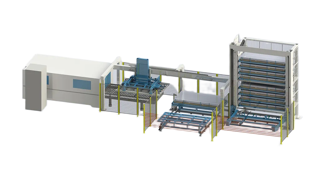
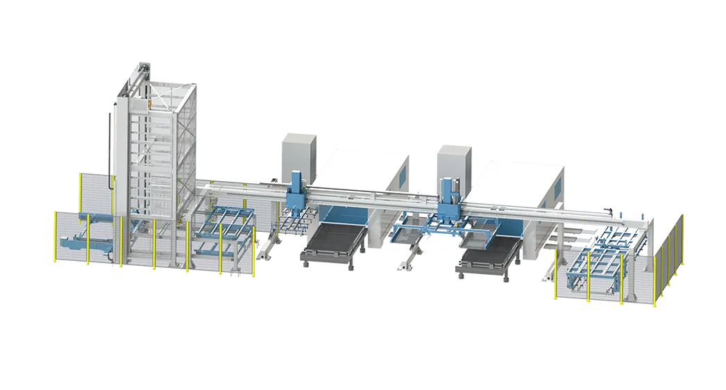
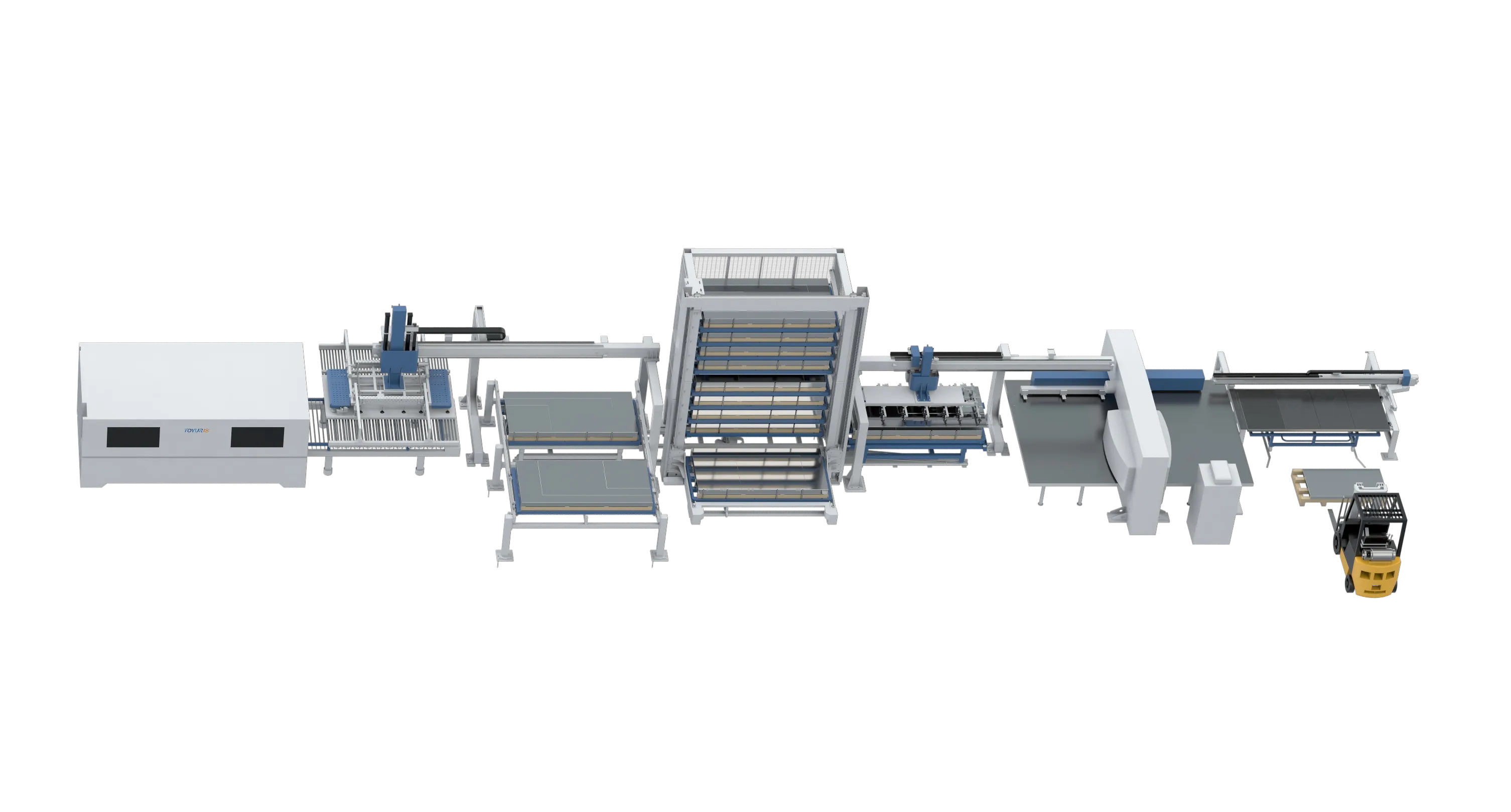
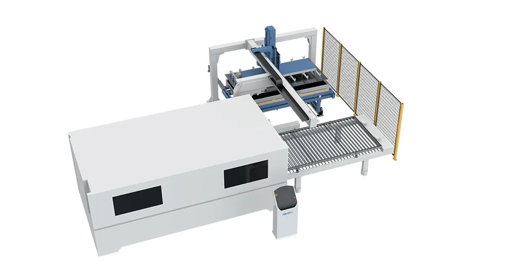
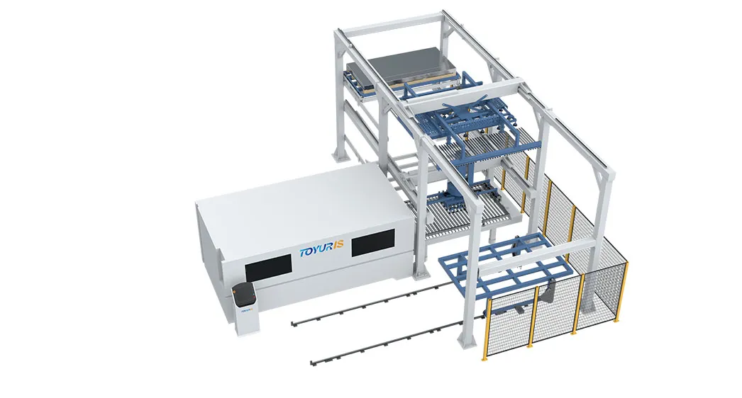
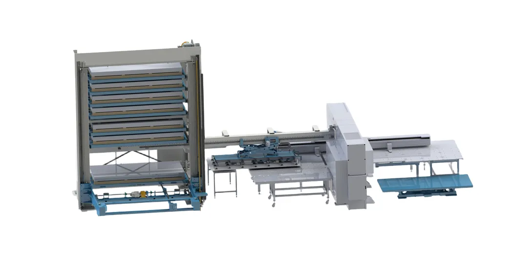
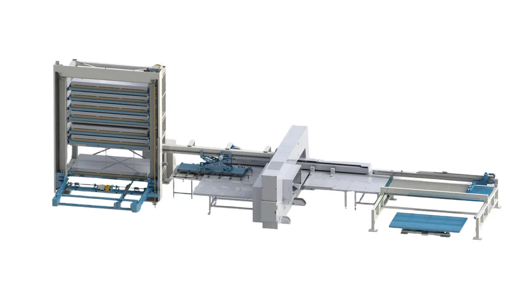
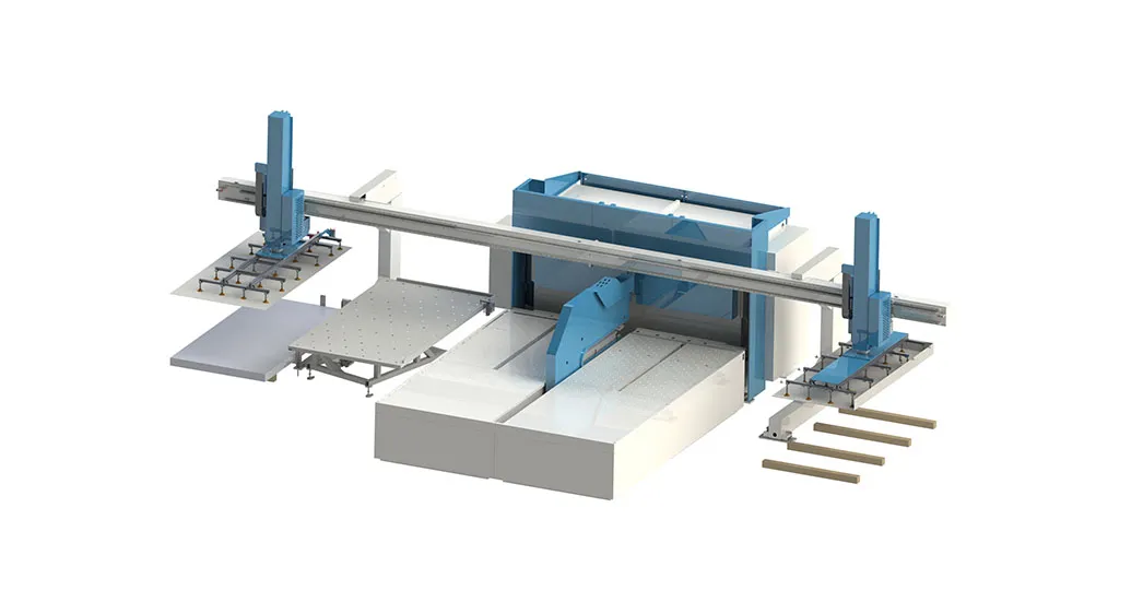
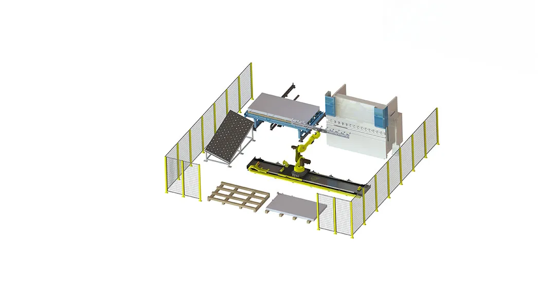
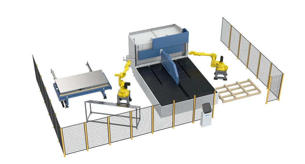
A high-performance sheet metal production line is not defined by the speed of a laser cutting machine, punch press or press brake in isolation. Its real performance depends on how efficiently material, production orders, machine capacity, tooling, WIP and manufacturing data move from one process to the next.
For manufacturers producing a high mix of sheet metal components, the engineering challenge is therefore much broader than automating individual machines. The production line must be designed as an integrated flow in which cutting, punching and bending operate according to a common production plan, material is delivered at the right time, and MES continuously communicates the status of every critical process.
A line can have highly automated equipment and still perform poorly if cutting produces faster than punching can consume, bending becomes a downstream bottleneck, material waits for transportation, or the MES cannot determine where a production order is physically located.
The objective of a smarter sheet metal production line is to synchronize process capacity, material flow, production scheduling and information flow so that the entire system produces more predictably with less unnecessary WIP and manual intervention.
The first engineering principle is simple: optimize the complete production flow rather than individual machines.
A typical sheet metal manufacturing route may look like:
Raw Material Storage → Material Retrieval → Laser Cutting → Punching/Forming → Buffer → Bending → Inspection → Welding/Assembly → Finished Goods
However, not every component follows the same route.
A simple enclosure panel may move directly from cutting to bending. Another component may require laser cutting, punching, tapping, forming and then bending. A third product may require inspection between operations.
This creates a routing problem.
A production system must understand the difference between:
Process sequence
Machine capability
Material requirements
Production priority
Batch quantity
Setup requirements
Tooling availability
Quality requirements
Downstream capacity
This is why a smart line should be designed around production routes, not simply around machines.
The equipment should serve the process architecture.
Machine cycle time is important, but it does not represent total production capacity.
Consider a simplified example.
A laser cutting machine can produce a batch in 30 minutes. A punching machine requires 45 minutes for the same batch, while bending requires 60 minutes.
If all three processes operate sequentially, the 60-minute bending process becomes the capacity constraint for that product route.
Increasing laser cutting speed further does not necessarily increase finished-product output.
In fact, it can increase WIP between cutting and bending.
The factory may then experience:
Higher cutting output → larger WIP → more handling → longer queues → bending congestion
This is a classic example of local optimization producing weaker system performance.
The correct engineering question is:
Which process limits the throughput of the complete production route?
Once the constraint is identified, capacity can be balanced around it.
A practical capacity model should consider more than nominal machine speed.
A simplified calculation is:
Effective Capacity = Available Time × Availability × Performance × Quality Yield
For example, a machine operating for 16 hours per day does not necessarily provide 16 hours of productive capacity.
If availability is 90%, performance is 85% and first-pass yield is 98%, effective productive time is substantially lower than the nominal 16 hours.
The same calculation should be performed for every major process.
| Process | Nominal Capacity | Availability | Performance | Quality | Effective Capacity |
|---|---|---|---|---|---|
| Laser Cutting | 16 h/day | 90% | 90% | 98% | 12.70 h/day |
| Punching | 16 h/day | 92% | 88% | 98% | 12.36 h/day |
| Bending | 16 h/day | 90% | 82% | 97% | 11.46 h/day |
These numbers are illustrative rather than production benchmarks.
The important principle is that the process with the lowest effective capacity becomes a candidate constraint.
But even this analysis is incomplete if material handling and setup are ignored.
A press brake may have adequate theoretical capacity while losing significant time to:
Tool changes
Program changes
Material waiting
Part orientation
Robot repositioning
Quality inspection
Manual loading
Unplanned interruptions
Therefore, the engineering model must include the entire operating cycle.
Laser cutting is often the first major processing stage after raw material preparation.
Its performance influences every downstream operation because it determines when blanks become available.
The engineering design should therefore consider more than laser power and cutting speed.
Important factors include:
Sheet dimensions
Material mix
Thickness range
Nesting strategy
Loading method
Unloading method
Remnant management
Part identification
Cutting batch size
Downstream process requirements
For a high-mix factory, the cutting process also needs to support production sequencing.
A large nesting job may maximize sheet utilization but create a problem if its parts cannot be consumed efficiently by downstream processes.
This is where automated laser cutting becomes part of a broader production architecture rather than simply an automated cutting machine.
The objective is to connect material preparation, cutting, unloading and downstream production requirements.
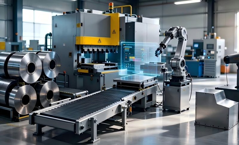
Nesting is traditionally evaluated according to material utilization.
That is important, but it is not the only objective.
Suppose one nesting program achieves 92% material utilization but produces a large batch of components that cannot immediately move into bending.
Another nesting strategy achieves 89% utilization but produces parts in a sequence that better matches downstream demand.
The second strategy may generate better overall factory performance.
This creates a broader optimization problem:
Material utilization + machine utilization + production flow + delivery requirements
The best nesting strategy may therefore not be the one that minimizes material scrap alone.
It should support the complete production plan.
Punching remains highly useful for applications requiring holes, louvers, forms, notches and other repeatable features.
The engineering question is whether punching should operate as:
An independent workstation
An automated cell
A combined cutting and punching process
A downstream operation supplied by an automated material system
The answer depends on product geometry, production volume and routing complexity.
For example, a factory with large quantities of standardized panels may benefit from highly automated punching.
A high-mix manufacturer may require flexible tooling and rapid job changeover instead.
A well-designed automated punch press should therefore be evaluated according to its role in the entire production route.
Important engineering questions include:
How are parts delivered to the machine?
How are jobs identified?
How long does setup take?
How are tools managed?
How are finished parts unloaded?
Where do completed parts go?
How does the next operation know they are ready?
These questions are more important to system performance than machine speed alone.
There is no universal rule.
Combination processing may make sense when the same part requires both technologies and minimizing material transfers creates a meaningful benefit.
Separate machines may be preferable when:
Product mix is high
Cutting and punching have different capacity requirements
Machines need to run independently
Production volumes vary significantly
Maintenance flexibility is important
Different product families require different process routes
The correct decision should be based on total cost and total flow, not the theoretical productivity of one machine.
Bending is different from many cutting operations because process time can vary significantly between parts.
Two components made from the same sheet thickness can have completely different bending requirements.
One may require three bends.
Another may require ten.
A complex component may also require:
Multiple tool configurations
Several part rotations
Special tooling
Manual intervention
Inspection
Robotic repositioning
This makes bending capacity difficult to estimate from average cycle time alone.
A factory should analyze bending demand by product family and route.
For example:
Required bending capacity = Σ (Part Quantity × Standard Bending Time) + Setup Time + Handling Time
This provides a more realistic estimate than simply counting the number of press brakes.
Automation around a press brake can reduce repetitive handling and improve consistency, but the engineering challenge becomes more complex when product variety increases.
A flexible bending cell needs to coordinate:
Part identification
Tool selection
Tool setup
Part loading
Part orientation
Bending sequence
Robot movement
Unloading
Inspection
Downstream routing
An automated sheet metal bending solution should therefore be evaluated as a complete cell.
The goal is not merely to make the press brake automatic.
The goal is to create a predictable interface between the previous process and the bending process.
Line balancing begins with identifying the required production takt.
A simplified takt calculation is:
Takt Time = Available Production Time ÷ Required Output
Suppose a factory has 14 effective production hours available per day and needs to complete 420 finished components.
The required average takt would be:
14 × 60 ÷ 420 = 2 minutes per component
This does not mean every machine must have a two-minute cycle.
Instead, the production system must provide enough aggregate capacity to satisfy the required output.
A process with a four-minute cycle may still meet demand if multiple machines or parallel cells are available.
This is why capacity planning should consider:
Number of machines
Parallel processing
Product mix
Setup time
Batch size
Availability
Shift pattern
This is one of the most common problems in automated sheet metal production.
If cutting produces faster than bending consumes parts, the difference accumulates as WIP.
At first, this may appear positive because the cutting machine has high utilization.
However, excessive WIP creates secondary costs:
More storage
More handling
More identification work
Higher risk of part mixing
Longer lead times
Greater space requirements
More difficult scheduling
A smarter system may intentionally slow or reschedule cutting to match downstream demand.
This may appear counterintuitive from a machine-utilization perspective.
But the objective is not maximum output from one machine.
It is maximum valuable finished-product throughput.
Buffers are necessary, but they should be controlled.
A buffer between cutting and bending can protect the bending process from short-term variation.
However, an unlimited buffer simply hides the bottleneck.
A useful buffer should have:
Defined capacity
Defined location
Part identification
FIFO or priority rules
Production status
Maximum residence time
Clear replenishment rules
MES can make this buffer visible.
For example, management may define:
Cutting-to-Bending WIP Target: 2–4 hours
If WIP reaches 8 hours, the system can flag a potential downstream bottleneck.
The exact value depends on the factory.
The important point is that WIP should be treated as a controlled production variable.
A machine cannot produce if the material is not available.
This seems obvious, but it is frequently overlooked during automation projects.
A highly automated laser cutter may still lose production time because:
Raw sheets are not available
Material is stored too far away
Remnants cannot be identified
Finished blanks are waiting for transport
Pallets are not available
Downstream staging areas are full
Therefore, the production-line design should include material logistics from the beginning.
The material flow should answer:
Where does material start?
Where does it go?
Who or what moves it?
Where is it temporarily stored?
How is it identified?
When is the next process notified?
These questions should be answered before equipment layout is finalized.
MES provides the information layer that connects physical production activities.
At the simplest level, the system should know:
Order → Part → Material → Process → Machine → Quantity → Status → Next Operation
For example:
A production order requires 800 enclosure panels.
MES releases the order.
The material system confirms the required sheet.
Laser cutting begins.
MES receives production status.
Completed blanks are transferred to the next process.
Punching completes the required features.
Bending receives the correct job sequence.
Inspection records quality results.
Finished components are released to assembly.
The system therefore maintains a digital thread across the production route.
A useful data structure should include at least:
| Data | Cutting | Punching | Bending | MES |
|---|---|---|---|---|
| Work order | ✓ | ✓ | ✓ | Master |
| Part number | ✓ | ✓ | ✓ | Master |
| Material | ✓ | ✓ | ✓ | Master |
| Thickness | ✓ | ✓ | ✓ | Master |
| Quantity | ✓ | ✓ | ✓ | Master |
| Program revision | ✓ | ✓ | ✓ | Controlled |
| Tooling | — | ✓ | ✓ | Managed |
| Start time | ✓ | ✓ | ✓ | Recorded |
| Completion time | ✓ | ✓ | ✓ | Recorded |
| Quality status | ✓ | ✓ | ✓ | Recorded |
| Next operation | ✓ | ✓ | ✓ | Managed |
| WIP location | ✓ | ✓ | ✓ | Tracked |
This creates a common production language.
Without this shared data structure, every department may have its own interpretation of production status.
Information can become a bottleneck just like material.
Imagine that a component has physically completed bending but the downstream department does not know whether the batch has passed inspection.
The component may sit idle even though the machine has finished its work.
A connected MES should automatically update:
Operation Completed → Quantity Confirmed → Quality Status → Next Operation Released
This reduces unnecessary communication and waiting.
The system should also record exceptions rather than forcing operators to manually explain every delay.
A useful bottleneck analysis should look at the complete route.
Track:
Queue time
Machine utilization
Cycle time
Setup time
Downtime
Material waiting
Quality holds
WIP accumulation
Schedule deviations
A process is a strong bottleneck candidate when demand consistently exceeds effective capacity.
However, a process with low machine utilization can also cause downstream delays if its availability is unpredictable.
Therefore, factories should distinguish between:
Capacity bottleneck
and
Reliability bottleneck
A machine may have enough nominal capacity but still disrupt production because of unpredictable downtime.
Cycle time measures how long a process takes.
Queue time measures how long a part waits.
In many factories, queue time is substantially larger.
For example:
Laser cutting: 12 minutes
Waiting for punching: 45 minutes
Punching: 8 minutes
Waiting for bending: 90 minutes
Bending: 15 minutes
Total processing time is only 35 minutes.
Total waiting time is 135 minutes.
If management focuses only on machine cycle time, it may miss the largest source of lead-time reduction.
This is why an intelligent production system should track both.
Setup time is particularly important in high-mix manufacturing.
Reducing setup may involve:
Standardized tooling
Automatic tool changes
Program management
Offline programming
Tool presetting
Job sequencing
Product-family scheduling
However, scheduling can also reduce setup.
If similar materials and tooling requirements are grouped intelligently, the factory may reduce the number of changes between jobs.
This means MES and production planning can contribute to equipment productivity without changing the machine itself.
Not necessarily.
A factory can achieve high machine utilization while creating excessive inventory.
For example:
Cutting utilization: 95%
Punching utilization: 90%
Bending utilization: 70%
At first glance, bending appears inefficient.
But if bending is the demand-limiting process, maintaining a controlled amount of capacity there may be necessary.
The correct KPI hierarchy should therefore consider:
Finished-product throughput → Delivery performance → Lead time → WIP → Bottleneck utilization → Individual machine utilization
Machine utilization remains important, but it should support the broader production objective.
A large sheet metal automation project does not necessarily need to be implemented all at once.
A practical roadmap may include four stages.
Establish part identification, routing, machine status and WIP visibility.
Automate the highest-impact manual operations such as loading, unloading and repetitive handling.
Connect storage, transportation and production staging.
Integrate MES, equipment, material handling and production scheduling.
This phased approach can reduce implementation risk and allow the factory to measure improvement after each stage.
The physical layout should reflect the production route.
Important considerations include:
Material receiving
Raw-material storage
Cutting cells
Punching cells
WIP buffers
Bending cells
Inspection
Welding
Assembly
Finished-goods storage
Maintenance access
Operator access
Safety zones
Material transport routes
The objective is to reduce unnecessary movement.
A U-shaped or cellular layout may work well for some product families, while a functional layout may remain more appropriate for highly variable production.
There is no universal layout.
The correct design depends on product routing and production volume.
The decision should be based on workload characteristics.
| Factor | Manual | Semi-Automatic | Highly Automated |
|---|---|---|---|
| Production volume | Low | Medium | Medium–High |
| Product variety | Very high | High | Medium–High |
| Labor availability | High | Medium | Lower |
| Material movement | Irregular | Repetitive | Highly repetitive |
| Production shifts | One | One–Two | Multi-shift |
| Traceability requirement | Basic | Moderate | High |
| Investment | Lower | Moderate | Higher |
| Flexibility | High | High | Depends on design |
Highly automated does not automatically mean better.
Automation should match production characteristics.
A high-mix factory with unpredictable routing may need flexible automation rather than maximum automation.
The baseline should be established before implementation.
Useful before-and-after measurements include:
Production lead time
WIP
Machine utilization
Queue time
Setup time
Material handling time
Labor touch time
Scrap rate
Rework rate
Schedule adherence
On-time delivery
Production throughput
For example, if automation reduces machine cycle time by 10% but lead time remains unchanged, the project may not have addressed the actual constraint.
If automation reduces queue time by 40%, the improvement may be much more meaningful even if machine cycle time changes only slightly.
A smart production line should be able to answer five questions continuously:
What should be produced next?
Where is the required material?
Which machine has the available capacity?
What is currently delaying the order?
What operation should happen next?
These questions connect planning, equipment and logistics.
Without this connection, automation remains a collection of automated machines.
With it, the factory begins to operate as an integrated production system.
Toyuris's Smart Sheet Metal Production Line concept can be understood as a system-level approach to sheet metal manufacturing.
The focus is not simply on installing a faster laser, a higher-speed punch press or an automated bending cell.
The engineering objective is to connect:
Processing Equipment + Material Flow + Production Data + MES + Scheduling + Quality Control
This architecture allows manufacturers to move from machine-level automation toward coordinated production.
For factories considering automation, the most useful starting point is therefore not a machine quotation alone.
It is a detailed analysis of:
Current production routes
Demand profile
Product mix
Process capacity
Bottlenecks
Material movement
WIP
Labor touch points
MES requirements
Future production growth
Once these variables are understood, equipment and automation can be selected around the production strategy.
Yes. The three processes can be connected through automated material handling, common production data, MES integration, robotic cells and controlled WIP buffers. The exact architecture depends on product routing, production volume and flexibility requirements.
It varies by factory. Common constraints include bending capacity, setup time, material availability, machine downtime, inspection, internal transportation and production scheduling. The bottleneck should be identified using actual capacity, queue and WIP data rather than machine specifications alone.
Not necessarily. Capacity should be balanced according to the production route and demand. Excessive upstream capacity can create unnecessary WIP if downstream operations cannot consume the output.
MES should track production orders, part numbers, material, process routes, machine status, quantities, program revisions, quality results, WIP location, production completion and exceptions.
The factory can reduce unnecessary WIP through better scheduling, smaller controlled batches, synchronized capacity, reliable material handling, clear buffer limits and MES-based production visibility. The goal is controlled WIP rather than eliminating every buffer.
No. Automation should match production volume, product variety, labor conditions, routing stability and return-on-investment requirements. High-mix factories often benefit from flexible automation rather than simply maximizing the number of automated operations.
Connecting laser cutting, punching and bending is fundamentally an engineering problem of flow synchronization.
The strongest sheet metal production lines do not measure success by the speed of individual machines alone. They balance process capacity, control WIP, reduce queue time, synchronize material movement, manage setup losses and maintain a continuous flow of production information through MES.
When the physical production line and digital production system are designed together, manufacturers gain a much clearer view of where capacity is being consumed, where orders are waiting and where automation can create measurable value.
The ultimate objective is a production system in which raw material, machines, WIP, operators, automated handling and production data work as one coordinated architecture.
That is what turns automated sheet metal equipment into a genuinely smarter sheet metal production line—and gives manufacturers a scalable foundation for higher throughput, shorter lead times and more predictable production performance.